
This page follows the Smart Microgrid+ architecture diagram. It is not an eighth area of the seven-area catalog.
Hande Smart Microgrid+
SEMS is the control center on the architecture diagram. It issues dispatch and receives operating status, so grid power, storage, diesel, gas, or methanol backup, and PV can supply one consumption site.
- Unified dispatch
- Coordinated output
- Stable power supply
- Grid controllable
Last reviewed 2026-10-27 (Asia/Shanghai)

Architecture
Redrawn on this page from the Smart Microgrid+ architecture. The public name is Hande Smart Microgrid+.
Hande Smart Microgrid+
- Unified dispatch
- Coordinated output
- Stable power supply
- Grid controllable
Control center
SEMS Intelligent Management System
Issues dispatch strategies and receives operating status.
Communication and control
- 01Power gridGrid connection
- 02Grid inverterPower regulation
- 03Grid-forming storageEnergy storage regulation
- 04Diesel, gas, or methanol setBackup generation
- 05Grid-forming PVPV access
- 06Consumption siteAggregated supply
Four layers
- 01
Communication
SEMS issues dispatch strategies and receives operating status.
- 02
Equipment
Coordinated operation of the grid, storage, generation, and PV.
- 03
Power supply
Multi-source power is aggregated and supplied to the site.
- 04
Application value
The diagram states the aim as supply reliability and cost-efficiency. No figure is printed.
Equipment on the diagram
The grid, inverter, storage, and backup-generation plates are dedicated stills. The PV and consumption-site frames are related equipment photographs, not a photovoltaic array.
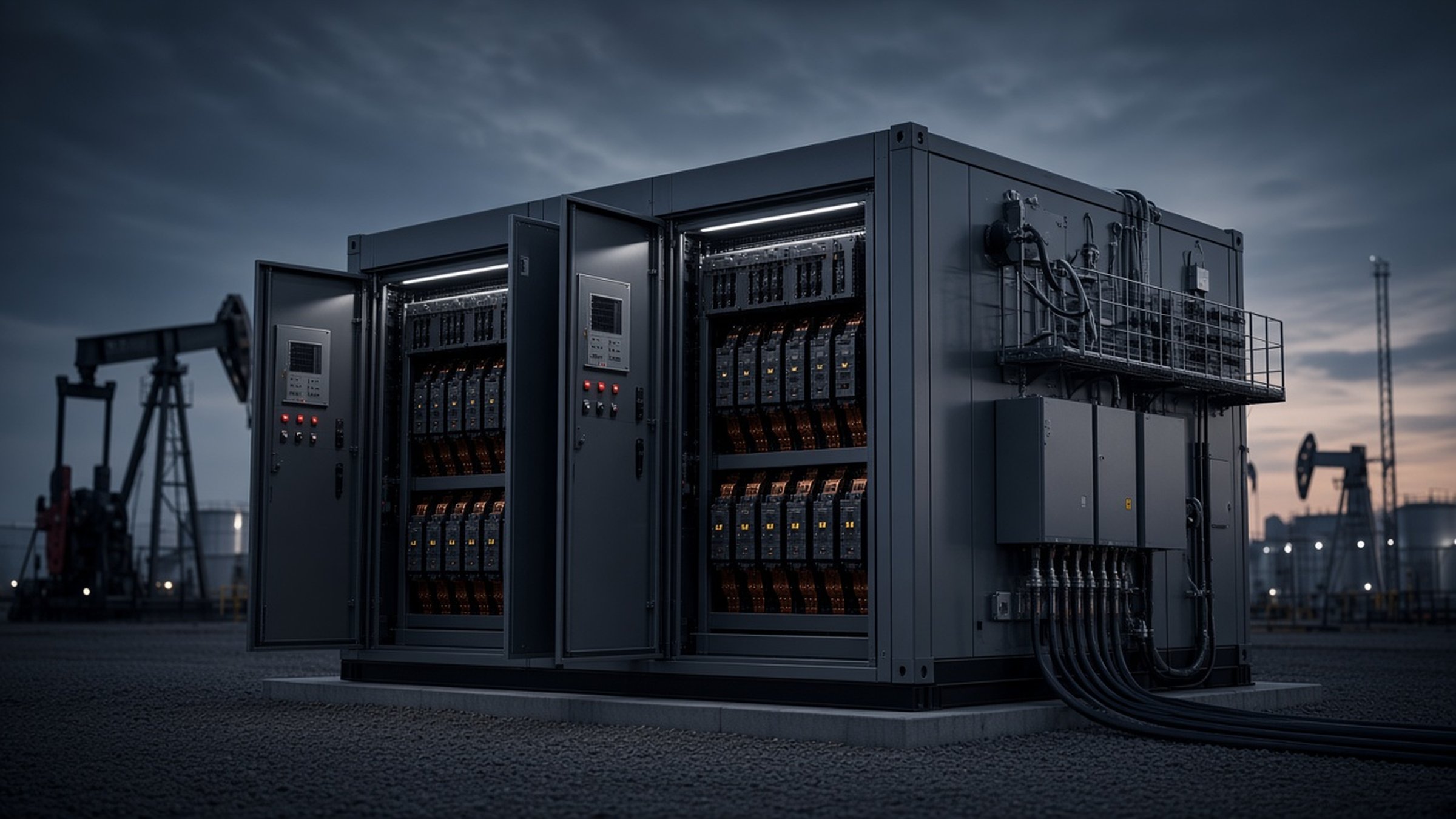
Power grid
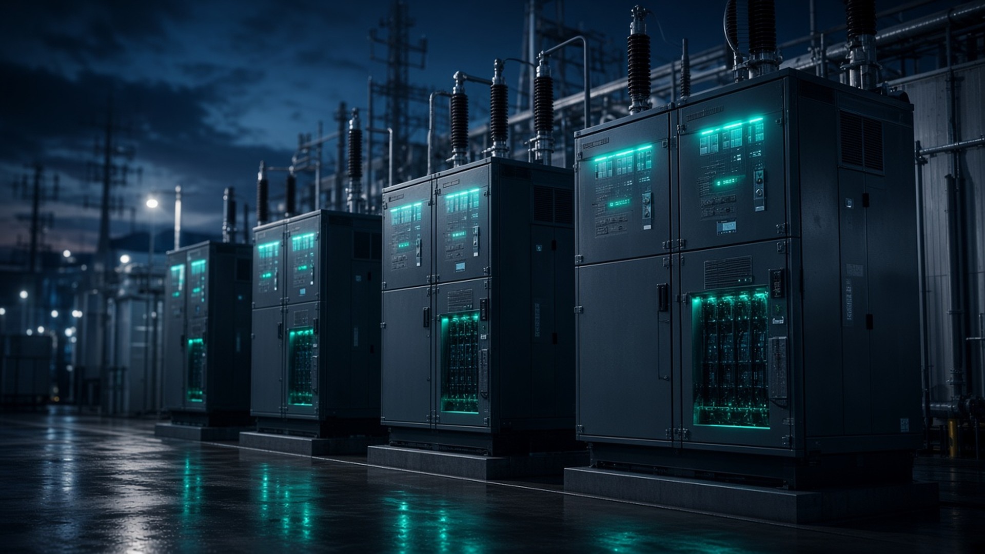
Grid inverter
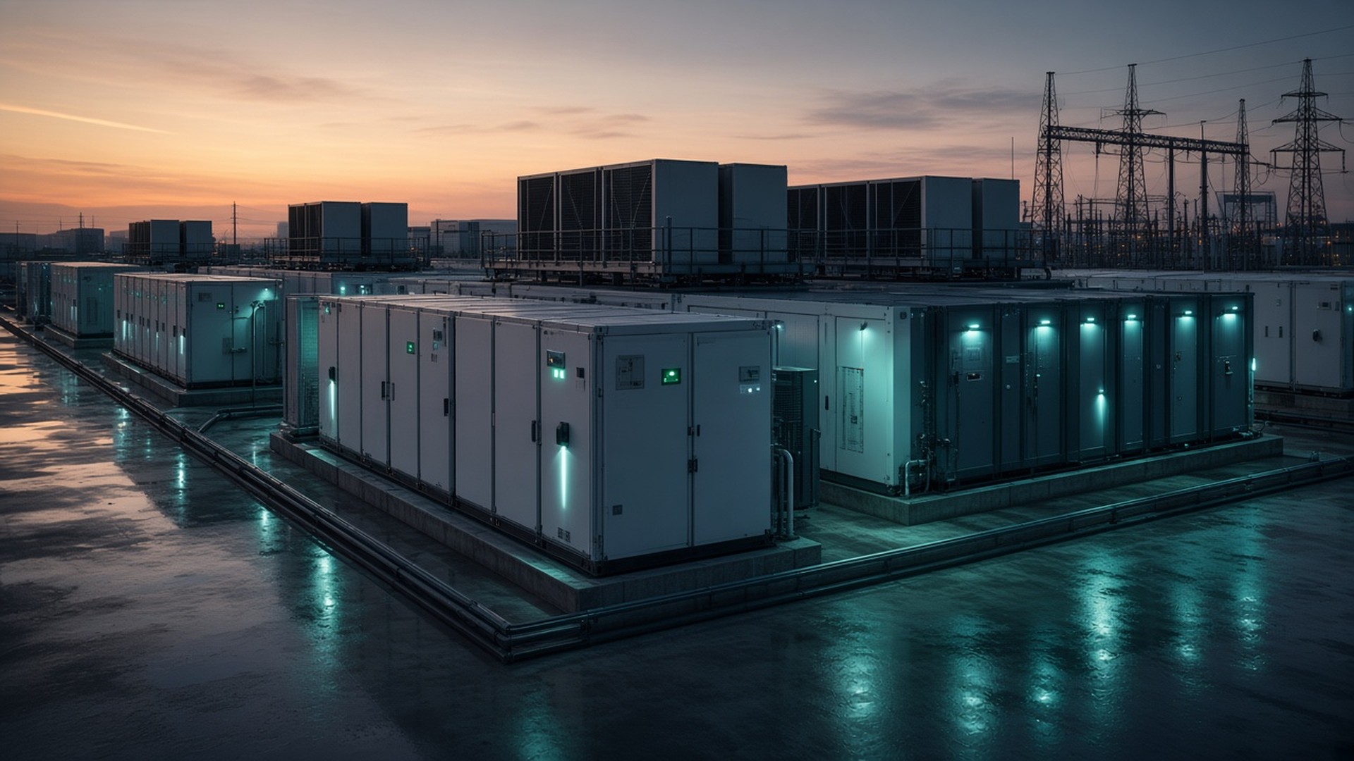
Grid-forming storage
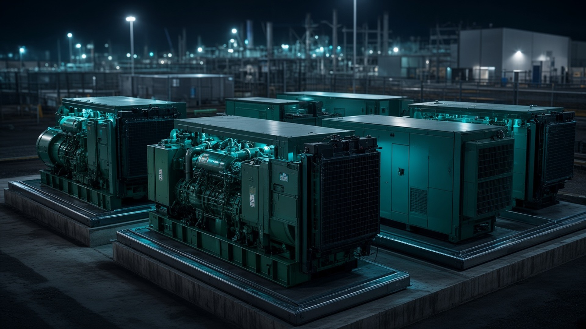
Backup generation
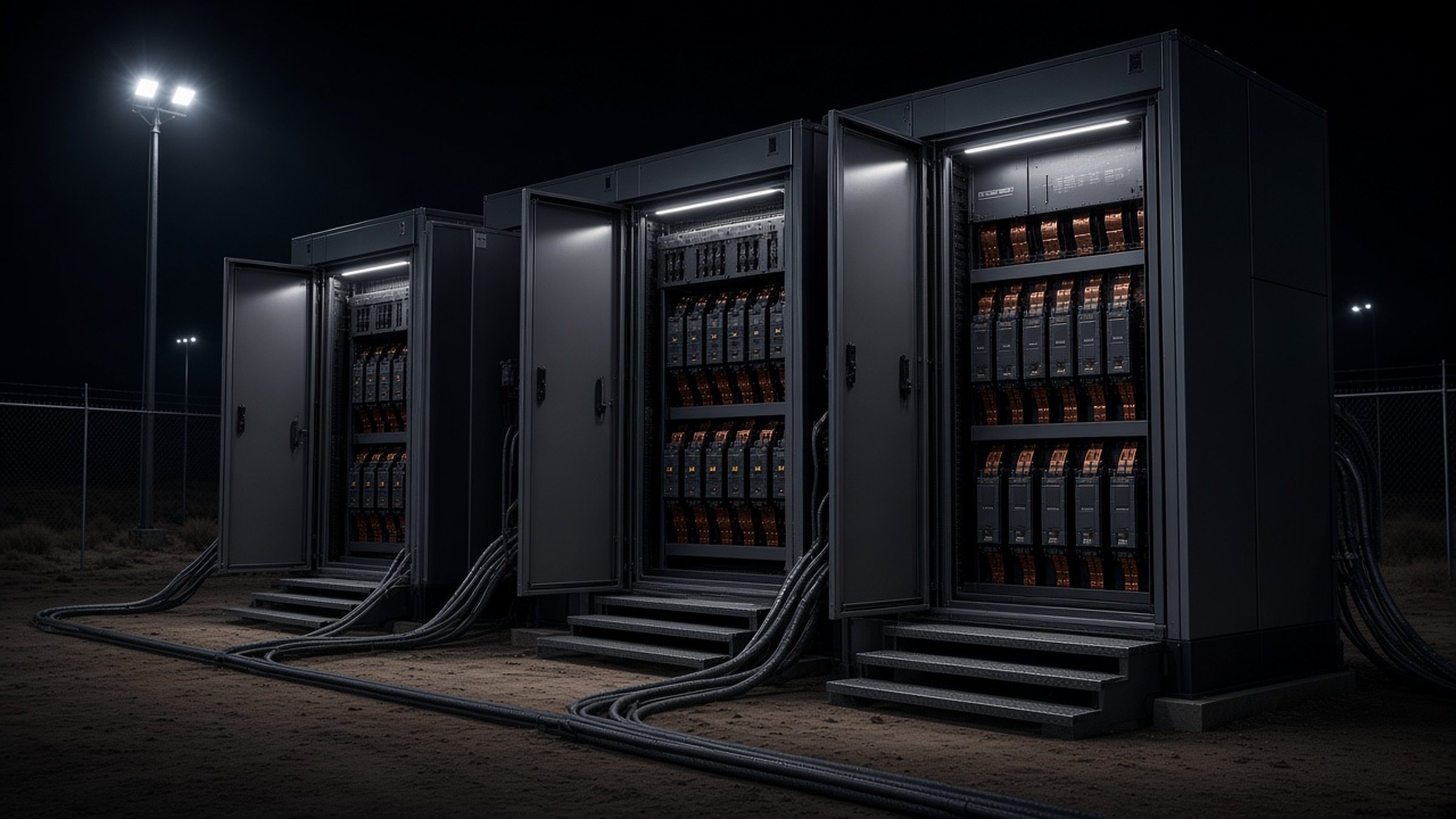
Grid-forming PV
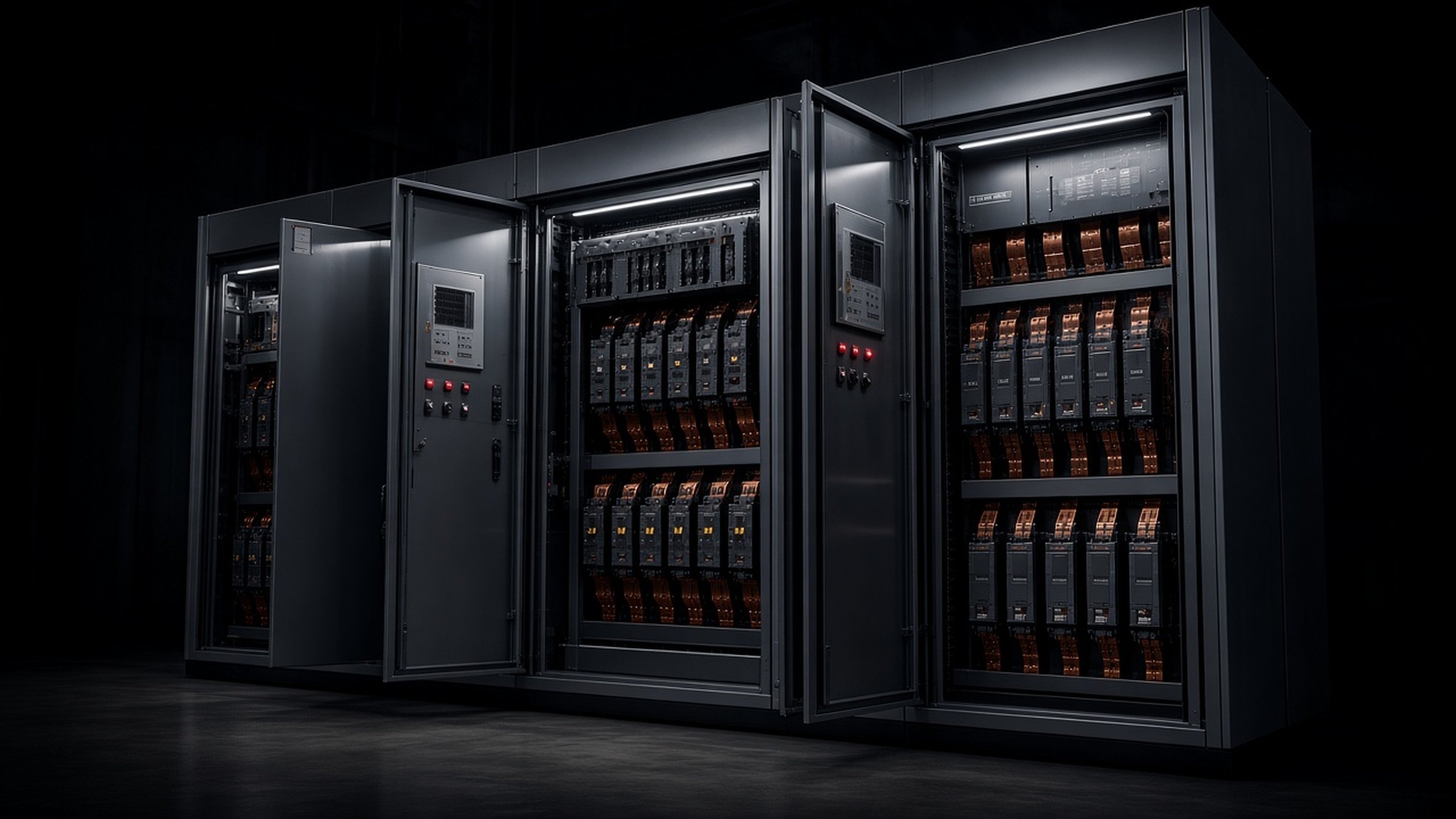
Consumption site


What those phrases mean here
Unified dispatch
SEMS is drawn as the control center. It issues dispatch strategies and receives operating status.
Coordinated output
The grid, storage, backup generation, and PV are drawn on one path and operate together.
Stable power supply
Multi-source power is aggregated and supplied to the consumption site. The diagram prints no reliability number.
Grid controllable
The grid inverter is the power-regulation device on the diagram, under the line that the grid is controllable.
How the site system is described
| Name | Role | Evidence note |
|---|---|---|
| Grid inverter | Power regulation between the grid and the rest of the path. | Named on the architecture diagram. |
| Grid-forming storage | Energy storage regulation on the same path. | Named on the architecture diagram. |
| Diesel, gas, or methanol set | Backup generation. | Named on the architecture diagram. |
| Grid-forming PV | PV access into the same path. | Named on the architecture diagram. |
In scope
- Name SEMS as the control center that issues dispatch and receives operating status.
- Name the equipment on the diagram: grid inverter, grid-forming storage, diesel, gas, or methanol backup, and grid-forming PV.
- Carry the aggregated supply to the consumption site.
Outside this offer
- Add a fuel figure, a savings percentage, or a customer name.
- Treat SEMS, storage, or PV as a printed catalog product line.
- Replace the catalog pages for power supply control, SVG, and TSF.
How the diagram is read
The drawing runs from the grid to the consumption site. SEMS sits above that path.
- The public grid connects through the grid inverter.
- The inverter regulates power between the grid and the rest of the yard.
- Grid-forming storage regulates energy on the same path.
- A diesel, gas, or methanol generator set is the backup source drawn on the diagram.
- Grid-forming photovoltaic joins through PV access.
- Multi-source power is aggregated and supplied to the consumption site.
Communication and control run between SEMS and the equipment. SEMS issues dispatch strategies and receives operating status.
Grid rooms, SVG, and TSF stay on power supply control, SVG and TSF, and rig grid power. For a site inquiry, use Request consultation.
Questions buyers ask
- What is Hande Smart Microgrid+?
- It is the architecture on this page. SEMS is the control center. The path runs from the grid, through the inverter, grid-forming storage, diesel, gas, or methanol backup, and grid-forming PV, to the consumption site. The four lines on the diagram are unified dispatch, coordinated output, stable power supply, and a controllable grid.
- How does this differ from the catalog power pages?
- Power supply control and SVG and TSF remain the printed grid scope. This page does not add those devices to a new catalog line, and it does not replace those pages. Rig grid power stays the catalog reading of grid, SVG, and TSF.
- What does SEMS do on this diagram?
- SEMS is the intelligent management system in the control center. It issues dispatch strategies and receives operating status over the communication and control path. That role is taken from the diagram. It is not a separate line in the seven-area catalog.
- Does this page quote a reliability or cost number?
- No. The application-value line on the diagram names supply reliability and cost-efficiency. This page does not add a percentage, a fuel figure, or a customer name. Use Request consultation for a site inquiry.